The sheet metal production process powers Australian industry– almost every kind of producer relies, in some way, on parts, specialized components, structures, or devices that is a direct outcome of sheet metal fabrication. From big commercial structures and supports to the most sensitive digital assemblies, sheet metal plays a key role.
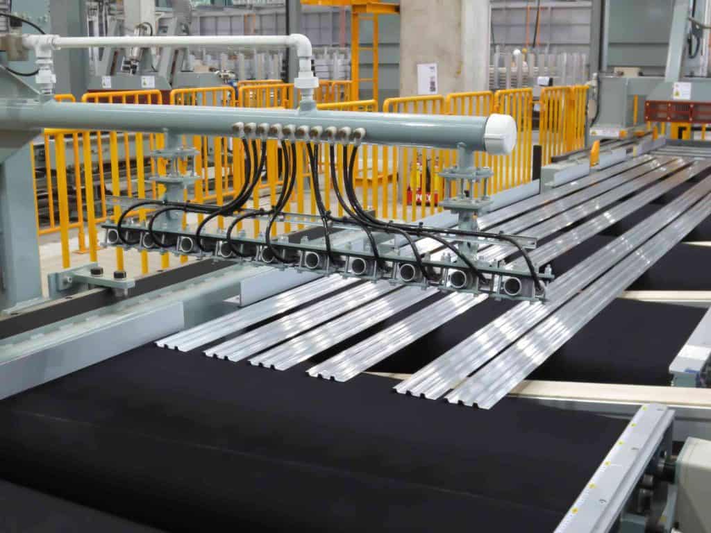
Table of Contents
Exactly what is the sheet metal working procedure?
Sheet metal fabrication is made up of almost as many individual processes and tools as the applications it serves. Their common goal, from laser cutting, to push brake forming, is to convert a sheet of metallic product into use for a particular task. This can be achieved with some methods.
Bending and Forming
The bending procedure in sheet metal utilizes unique tools, such as press brakes, to produce U flexes, V flexes, and custom forms from flat metal sheets. Folding, machining, and stamping are all typical methods to flex or form metal. Rotary and elastomer flexing can produce brand-new shapes even with ended up and fragile surface areas, while punching is an example of precision fabrication with the use of a die.
Laser Cutting
The sheet metal cutting process can involve tools of all kinds, from basic to advanced. Customized cutting of specialty alloys, rare-earth elements, and particularly tough materials frequently needs the use of laser cutting. This procedure permits increased accuracy and precision when cutting item, along with increased effectiveness as computer system helped programs guarantee that the most effective patterns are used.
Joining
Frequently, a part can not be created from a single, flat sheet of metal– some form of welding process or assembly should bring two or more private parts together. Fascinating, adhesives, brazing, and welding are all different methods to create a single, bound metallic part.
Finishing
When a sheet of metal has been changed into a cut, formed, bent, or otherwise complete piece, it can be ended up and safeguarded with paint, powder finishes, silk screening, and other custom surface treatments. A few of these automated ending up treatments are designed to give the metal unique homes, such as additional strength, conductivity, or resistance to corrosion or particular chemicals.
Once a sheet of metal has been transformed into a cut, formed, bent, or otherwise total piece, it can be ended up and secured with paint, powder coatings, silk screening, and other custom-made surface treatments. Some of these automated ending up treatments are created to offer the metal unique residential or commercial properties, such as additional strength, conductivity, or resistance to deterioration or particular chemicals.
Material Selection
Some materials are simpler to process than others, making product choice a crucial step in any sheet metal fabrication procedure. Aside from getting the best last expense and performance fit, making a mindful, well-researched product option can save considerable cash, time, and energy on a job.
Product option can also assist figure out the very best producer for your task. Many manufacturers concentrate on particular materials or pride themselves available a full selection of services in one center. Sheet metal processes such as accuracy machining, precision forming, and laser cutting for exceptionally tight tolerances are just some of the unique services available from specialized makers.
To find out more about sheet metal fabrication processes or the benefits of specific procedures or products, contact the team at Australian General Engineering today.
Complex Sheet Metal Fabrication
Australian General Engineering team is known throughout the medical sector for our ingenious design services and precision manufacturing. We offer turnkey options for the most challenging engineering and fabrication difficulties, shown by a project we just recently completed for Soteria Medical, a company in the medical market.
Requiring help with a custom-made task, Soteria Medical approached our team with a spoken job description however very few specifics regarding the item they needed to produce. They trusted us to create the very best possible style, develop a plan for complete production, and provide a premium final product.
Creating a Design
Our client initially bought a medical cabinet that did not fulfill all of their requirements; they required a new cabinet to change the original purchase, but did not have any idea illustrations to outline their wanted replacement item.
When we met with the client’s group, they could only supply a general principle of the proposed cabinet’s specifications, which needed to include a variety of specialized medical equipment. Paying attention to the information of our client’s requirements, we equated their verbal ideas into CAD illustrations based upon descriptions. Soteria approved us full creative license to create a style that would employ our diverse manufacturing capabilities to fabricate a customized cabinet efficient in real estate and securing sensitive devices.
Hassle-free In-house Manufacturing
With our innovative style abilities, extremely experienced workers, and advanced equipment, the Australian General Engineering team performed all style and production in-house. This supplied significant time- and cost-savings when compared with outsourcing the fabrication process.
After finishing detailed plans, our staff members utilized sheet metal forming and machining, in addition to welding and automated laser cutting, to manufacture the cabinet. We took special care to not only develop the most accurate and functional cabinet possible, but to also supply an aesthetically pleasing item with a smooth, long lasting finish.
A Quality Final Product.
After the style, manufacturing, and delivery procedures were total, we received a radiant report back from our consumer.
Our cabinet supplied all of the performance that they needed, in addition to impressive craftsmanship. It satisfied all the requirements that their initial design had actually been not able to satisfy– and was developed for a lower cost than the initial producer. Due to the fact that we structured the manufacturing procedure by completing the whole project in our own center, we offered significant expense savings and a fast lead time for our customer.
A similar blog post we wrote Welding Terminology and Abbreviations
Australian General Engineering is a Melbourne based General Engineering business that provides a comprehensive range of complete sheet metal fabrication Services