The K-factor and the Y-factor assess the sheet metal's response to bending and the degree to which it can be bent. Metal sheets contract at the top and stretch at the bottom when bent. The neutral radius delineates the innermost boundary between these two phases within the metal. This border exactly divides the thickness of the metal while the metal is flat, but it moves when the metal is bent.
Calculated from the neutral diameter divided by the material's thickness on standard charts, the K-factor ranges from 0.3 to 0.5. The Y-factor is similar to the K-factor, but it is more precise because it accounts for the stresses present in the material.
To determine how much flat sheet metal must be produced to make a bend with a given radius and angle, designers employ constants known as the Y factor and the K factor. The location of the neutral bend line about the thickness of a sheet of metal is used to determine the Y factor and the K factor. The location of the neutral bending line varies in part due to the sheet metal utilised. References in numbers are from zero to one. The Y and K factors can take on negative values, with lower values indicating a softer material. The developed length is equal to the length of a neutral bending line.
The K factor is defined as the ratio of the thickness of a material to the length from the neutrality bend line to the inner bend radius. The K factor formula is K factor = /T. To calculate Y, multiply K by /2; the result is Y. The Y-factor is set at 0.50 by default.
Austgen Steel fabrication Melbourne
Table of Contents
What’s K-Factor?
The K-factor describes the relationship between the neutral axis and the thickness of a sheet of metal. As a metal sheet is bent, the material on the outside of the bend expands while the material on the inside contracts. The neutral axis shifts from its initial location at 50 per cent of the material thickness towards the inside surface of the bend, but else remains unchanged. Elongation happens during bending because the neutral axis moves, but the length stays the same. The thickness, inner bend radius, and forming method all affect how much the neutral axis moves.
You can calculate the new location of the neutral axis by multiplying the thickness of the material by the standard default K-factor value of 0.446. Essentially, we are trying to fit the length measurement from a bigger radius onto a smaller one. By squeezing the same amount of material into a smaller radius, we have elongation rather than the previously assumed additional length.
Think about using a material thickness of 0.060 inches. To get 0.0268 in, we multiply by a K-factor of 0.446. Measured from the inside of the curve, the axis has moved from 0.030 inches to 0.0268 inches. In other words, the axis had an inward shift of 0.0032 inches. That's where we'll get the data we need to figure out how much the arc should bend.
It is important to remember that the K-factor varies depending on the type of material, the forming method, and the connection between the bend radius and the material thickness. These subsequently affect the overall amount of elongation and the necessary bend deductions.
What’s Y-Factor?
Like the more familiar K-Factor, the Y-Factor is just a tweakable factor. You may calculate it by multiplying 0.5 by pi, which is half of the K-Factor.
The formula for Y is: dfrac(K)/c(pi2)
As far as we know, PTC's Pro-Engineer is the only product that uses the Y-Factor. The default value of is.5, which results in a K-Factor of about.318; this is not a horrible value to work with when designing with sheet metal. Knowing the values of the Y and K-Factors will help you predict the amount of stretching a part will undergo when you go from a flat pattern to a 3D-printed object. Unfortunately, the Y-Factor almost always requires editing for fully accurate parts and designs. Several simple techniques exist for this purpose.
As a starting step, you might try modifying the 'Material' file. The PTC INITIAL BEND Y FACTOR parameter in the Materials Definition screen is where you'll want to make this adjustment. You can now tailor the Y-Factor of your materials to meet your needs. It seems to be a frequent constraint of design software that you can't provide custom values for individual gauges, although we could be wrong. When designing components, being able to specify a factor for every material may get you very near to perfect. K-Factors are permanent; thus, if you set some material and remove it, the K-Factor will still be the same as before. This consideration is important when making substantive changes.
The 'Set Up' option provides a second means of modifying the Y-Factor. Initiating the Y-Factor in this way will set a new standard. You may then use the new Y-Factor as the default for any new components you make following the initial setup. However, since various materials have varying Y-Factor requirements, this approach might not be the most effective. To review our previous post just on K-Factor, complete with diagrams and explanatory text, click here.
As a third alternative, you can change your configuration file to set the Y-Factor for all new components properly. This is functionally equivalent to the "Set Up" command and should be avoided if you need precise parts from various materials.
Each feature's Y-Factors can be adjusted for greater precision in your designs. This can be helpful when the neutral axis is increasingly misaligned with the correct Bend Allowances, like at the extremes of Bend Angles or radii.
The Y-Factor is not required if you use a bend table in place of the program's calculations, which is possible in Pro-Sheet Metal and most design applications. Based on the indispensable Machinist's Handbook, tables like these are an essential tool for any industrial engineer. These tables, in turn, were founded on empirical evidence. Unfortunately, to the best of our knowledge, there is no universal formula for determining the flatness of a pattern.
Check out Austgens INDUSTRY SECTORS
How Many Different Ways Can Metal Be Bent?
When determining the total elongation for a specific type of bend, known as the bend deduction, bending and bend formation play crucial roles. Consequently, the mathematical values utilised in the calculation will be influenced by the procedures employed.
Bending a sheet of metal is an example of a forming process. When sheets are plastically distorted to alter their form. During bending, the tension placed on the material exceeds its yield strength but falls short of its ultimate tensile strength.
The overall length of a sheet of metal is greater after it has been bent than when it was flat. Depending on the desired effect, a bend deduction and bend allowance might be used to express this length difference.
Methods of Bending Metal
Metal can be bent into four distinct shapes depending on the radius chosen: sharp, minimal, perfect, and perfect radius. The metal is bent until its radius is the shortest it can be without creasing, which is called the minimum radius bend. You can spot bends with a precise radius and a razor's edge using this number.
A perfect bend has a radius greater than the minimum radius and less than or equal to 125 percentage points of a metal's thickness. A radius bend is produced when the metal is bent past 125% of its thickness.
And then there are severe turns on the opposite end of the spectrum. They appear when the metal is bent past its critical radius, creating a sharp crease.
For starters, let's take a step back and speak about the various sheet metal bends that can be made. Don't worry; the K-factor will be introduced to the conversation soon. Don't worry about me for the time being.
There are four distinct varieties of bends, including minimum-radius, acute, perfect, and radius. A minimum-radius bend is one whose radius equals the smallest interior radius that may be achieved without crimping the material. If you try to create a radius lower than the absolute minimum, you will fold the radius in the middle, resulting in an acute bend.
During bending, the radius should be exactly or very close to the thickness of the material. In this case, the minimum radius value is 5% of the material thickness, and the maximum radius value is 125 percentage points of the material thickness. Therefore, a radius bend is defined as having a radius greater than or equal to 125% of the thickness of the material.
When calculating a curve, even a severe one, the least radius you may use is the fixed distance radius when you want your figures to pay out in practice. Remember that a steep bend in the air is normally very destructive to uniformity. The crease at the bend's centre will exaggerate the effect if the material's grain orientation, toughness, density, or tensile strength varies.
Your ability to control the area around your nose when you punch is also relevant. At an inside radius of 0.078 in., punch tip radii of 1/16 in. (0.062 in.), 1/32 in. (0.032 in.), and 1/64 throughout. (0.015 in.) are too acute. The overall amount the angle variation will increase significantly when the punched nose radius decreases relative to the thickness of the material.
Allowance for metal bending
By entering the Sheet's thickness and starting length into the corresponding cells on the left, we can determine the bend tolerance, the K factor, and the derived coefficient, the Y factor. Next, insert the inner radius and flanges A and B after bending the Sheet. The angle of the bend is 90 degrees.
You might think of bend allowance as the opposite of the bend deduction. For example, what must be added to a Flange length (A1 and B1) to create a flat length?
The Bend Allowance is calculated as follows: Flat Length = A1 + B1.
The terms "bend allowance" and "bend deduction" are reciprocal. Two times the outside setback equals the sum of the bend allowance and the bend deduction.
The addition of BA and BD equals two times the OSSB.
Distance Beyond Wall = (Tan(A/2)) x (T + R)
Where ;
BC; Breaking Capacity
"BD"; "Bend Deduction"
In other words, an external setback
Angular Deflection
The thickness of the Sheet
R = Radius of Curve Inside
Bend Deduction
The bending process adds length to the sheet metal component.
When a material bends, the area closest to the centre of the bend is squeezed while the area furthest from the centre is stretched. Because of this, sheet metal components have a larger overall surface area. To rephrase, the Flat Length of the sheet metal is less important than the Whole Length (A + B).
Bend Deduction refers to the reduction in overall length compared to the original flat length.
Check out CNC Laser Cutting Fabrication – A Brief Description & Process
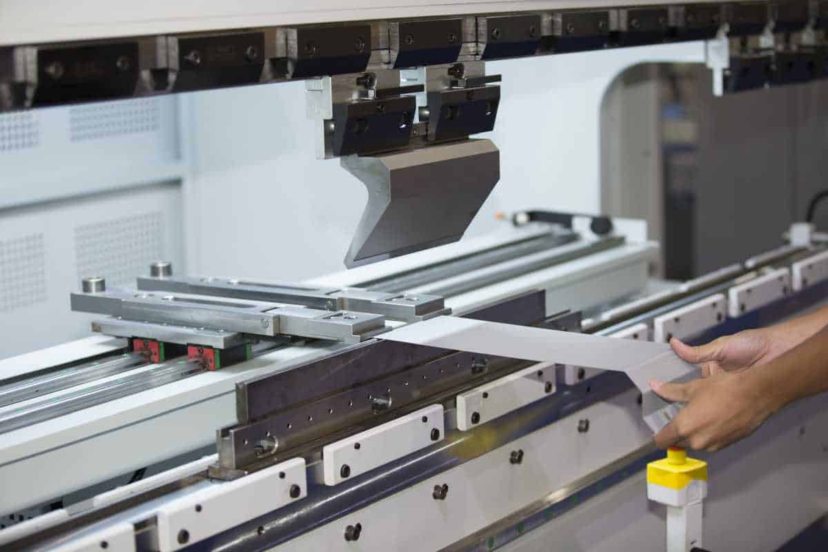
What’s Metal Bending?
Likewise, the method through which the metal is bent is significant. Coining, bottom bending, and air bending are the three primary techniques available for shaping. The practice of issuing coins is the oldest but has mostly fallen by the wayside in modern times. In this procedure, a punched nose presses into the metal and past the neutral radius. As coining reduces thickness, it weakens the material.
While bottom bending is comparable to coining, it does not cause permanent damage to the substrate. Instead of the punch nose pressing into the metal, the metal is forced to press around the punch nose. Like with coining, the radius within the bend equals the radius of a punched nose.
There is no one-to-one relationship between the punched nose radius and the bend radius in air bending. Instead, the radius of the bend is expressed as a fraction of the die's diameter. The 20% rule, which employs percentages of about 20% for various metals, is popular among engineers. For example, the percentage can be anything from 20% to 22% for 304 stainless steel but is often between 13% and 15% for H-series soft aluminium.
However, bottom bending & coining are not the same things. The punch nose is driven into the material through coining, entering the neutral axis. First, from the bottom of a die, bottoming occurs at the height of around 20% more than the material thickness.
It's possible that your stamping press's die sets are coining the metal or just going halfway through the thickness of the material. Bottom bending, which happens again at around 20% above the material thickness, is the likely alternative. Both methods constrain the material to a specific radius. However, one does so more tightly than the other. Whether your diagrams depict or coining or have a sharp, minimal, perfect, or radius bend, the radius is always calculated based on the punch nose value.
Yet, in the case of aerated structures, this is not the case. The radius of the finished product in an airborne form is a function of the size of the die cavity. The interior radius is calculated by dividing the whole width of the die by the distance an air-formed bend travels. The fraction relies on the tensile strength of the material. The "20 per cent rule" describes this situation. Yet, since the percentage shifts depending on the material and tensile strength, the name is just a label.
In the case of 304 stainless steel, the radius formed is approximately 20–22% of the die width, while the radius formed in 5052-H32 aluminium is approximately 13%–15% of the die width. Therefore, the interior radius should be smaller when working with softer materials.
However, most of our calculations, such as the 20% rule, use 60-KSI cold or flu steel as the basic material. The width is rounded off with that material between 15% and 17% of the die. We use the midpoint as our starting point (16%) and make any required adjustments. Let's pretend we have some 120-KSI material that needs to be processed. Our 120 KSI sheet will air-form to a rough radius twice that of cold or flu steel—or 32% of the die opening (16% 2). This is a significant increase over the 60 KSI for our baseline material.
In What Ways Can K- And Y-Factors Be Determined?
You may determine their K-factors and Y-factors for different metals, but doing so manually is more time-consuming and error-prone than utilising the basic ratio provided by reference materials.
Check out General Metal Fabrication – A Brief Description & Process
Determine K-factor?
Obtaining the K-factor value requires several measurements using various metal components. It would be best if you had the unbent and bent lengths and the interior radius. Gauge pins, radius gauges, and optical comparators can be used to obtain these measurements. It all starts with calculating the BA, or bend allowance, using these details.
The sheet elongation calculation relies heavily on the bend allowance. That which extends from the origin to the terminus of the arc formed by the bend is known as the neutral fibre's length.
Then, take readings for the included angle and the complimentary bend angle, calculated by subtracting 180 degrees from the included angle. The K-factor in sheet metal bending can be determined after the layer thickness, Mt is known.
K-factor can be calculated by dividing the difference between the ratio of Ir to Mt and the product of pi, Mt, and the complementary bend angle. This formula can be written down in math as:
The formula for the K-factor is: K = (180) (( x Complementary Bend Angle x Mt) - (Ir Mt)].
Determine Y-factor?
The Y-factor cannot be calculated without the K-factor first. Multiplying the K-factor by pi and dividing that value by two yields a Y-factor.
K-factor times two yields the Y-factor.
What Are K- And Y-Factors for Developing Custom Metal Parts?
Because not all materials include K-factors and Y-factors on the chart, you will need to figure out these values using your chosen metal. If you use the equations above to personalise your designs, you won't have to settle with common values. You can now expand beyond the bounds of tabular norms with this skill.
Two factors can be used to determine the amount of a bend deduction: the K-factor and the Y-factor. First, from Bend Allowance as well as the OSSB, we derive the Bend Deduction. To calculate the bend deduction (BD), multiply an outside setback by two and deduct the bending allowance from the resulting product. The OSSB is calculated by dividing two times the product of the inside radius as well as the thickness of the material by the tangent of a bend angle.
With this formula: BD = (2 x OSSB) - BA
OSSB = tan(bend angle 2) x (Ir + Mt).
You'll want to remember that BA is the difference between the formed and flat dimensions. K-factors and Y-factors can also be used to derive this value.
Assuming a K-factor, the BA is calculated as follows: BA = [( 180) x Ir] + [( 180) x K-factor] x Mt
Adjusted for Y, the BA becomes BA = [( 2) x Ir + (Y-factor x Mt)].
If you know the K-factor and Y-factor, you can use these formulas to derive the bend deduction.
Conclusion
The sheet metal's response to bending and the amount it can be bent are evaluated using the K-factor and Y-factor. Material thickness in relation to the distance along the neutral bending axis to the inner bending radius is the K-factor. In contrast to the K-factor, the Y-factor is more accurate because it takes into account the material's stresses. Sheet metal used plays a role in determining the location of the neutral bending line. For softer materials, a lower value for the Y and K factors is preferable.
By multiplying the thickness of the material by the default K-factor value of 0.446, the Y-Factor can be used to determine where the neutral axis has shifted to. The K-factor varies with the properties of the material, the forming technique, and the relationship between the bend radius and the thickness of the material. Only PTC's Pro-Engineer makes use of the Y-Factor. It is possible to estimate how much a part will stretch when converted from a flat pattern to a 3D-printed object by knowing its Y and K-Factor values. There are a few easy methods that can be used for this.
You can modify the Y-Factor of your materials by adjusting the PTC INITIAL BEND Y FACTOR parameter on the Materials Definition screen. Even though the "Set Up" button can be used to establish a new norm for new components, it may not be optimal because different materials have different Y-Factor requirements. Using a bend table in place of the program's calculations eliminates the need for the Y-Factor and is an option in Pro-Sheet Metal and many other design programmes. There is no one-size-fits-all method for figuring out whether or not a pattern is flat. An example of a forming process in which the tension applied to the material exceeds its yield strength but is less than its ultimate tensile strength is the bending of a sheet of metal.
There are four distinct forms that can be achieved when bending metal: sharp, minimal, perfect, and perfect radius. When bending metal, a perfect bend occurs when the radius is greater than the minimum radius and less than or equal to 125% of the metal's thickness, while a radius bend occurs when the radius exceeds 125% of the metal's thickness. Soon, we will be discussing the K-factor. Important facts include: when calculating a curve, the least radius used is the fixed distance radius; if the grain orientation, toughness, density, or tensile strength of the material varies, the crease at the bend's centre will amplify the effect; and so on. After bending the Sheet, the inner radius and flanges A and B need to be inserted into the corresponding cells on the left to determine the bend allowance.
After being bent, a sheet metal part gains length, making the Total Length (A + B) more relevant than the Flat Length. The term "Bend Deduction" describes a shortening of the entire object. You can form metal in a variety of ways, but your primary options are coining and bottom bending or air bending. Coins are the oldest form of currency, but they are rarely used today. It requires pushing past the neutral radius with a punched nose into the metal.
Similar to coining, bottom bending doesn't leave any lasting damage to the substrate. Since the radius of the bend is expressed as a fraction of the die's diameter, the punched nose radius and the bend radius are not directly proportional to one another in air bending. There is no universal "20 percent rule" because the percentage changes with the material and tensile strength. Sheet metal bending K-factor and Y-factor can be measured with known metal components. To determine the K-factor, divide the ratio of Ir to Mt by the product of pi, Mt, and the complementary bend angle.
Without measurements from gauge pins, radius gauges, and optical comparators, the Y-factor cannot be calculated. The K-factor and the Y-factor are used to calculate the amount of a bend deduction. Multiplying an exterior setback by two and subtracting the bending allowance yields the Bend Deduction (BD). To determine the OSSB, divide the tangent of a bend angle by two times the product of the inside radius and the thickness of the material. It is also possible to calculate this using K-factors and Y-factors.
Content Summary
- The K-factor and the Y-factor assess the sheet metal's response to bending and the degree to which it can be bent.
- The location of the neutral bend line about the thickness of a sheet of metal is used to determine the Y factor and the K factor.
- The K factor is defined as the ratio of the thickness of a material to the length from the neutrality bend line to the inner bend radius.
- The K-factor describes the relationship between the neutral axis and the thickness of a sheet of metal.
- You can calculate the new location of the neutral axis by multiplying the thickness of the material by the standard default K-factor value of 0.446.
- To get 0.0268 in, we multiply by a K-factor of 0.446.
- Measured from the inside of the curve, the axis has moved from 0.030 inches to 0.0268 inches.
- That's where we'll get the data we need to figure out how much the arc should bend.
- It is important to remember that the K-factor varies depending on the type of material, the forming method, and the connection between the bend radius and the material thickness.
- These subsequently affect the overall amount of elongation and the necessary bend deductions.
- Like the more familiar K-Factor, the Y-Factor is just a tweakable factor.
- Knowing the values of the Y and K-Factors will help you predict the amount of stretching a part will undergo when you go from a flat pattern to a 3D-printed object.
- The PTC INITIAL BEND Y FACTOR parameter in the Materials Definition screen is where you'll want to make this adjustment.
- You can now tailor the Y-Factor of your materials to meet your needs.
- The 'Set Up' option provides a second means of modifying the Y-Factor.
- Initiating the Y-Factor in this way will set a new standard.
- As a third alternative, you can change your configuration file to set the Y-Factor for all new components properly.
- This is functionally equivalent to the "Set Up" command and should be avoided if you need precise parts from various materials.
- Each feature's Y-Factors can be adjusted for greater precision in your designs.
- The Y-Factor is not required if you use a bend table in place of the program's calculations, which is possible in Pro-Sheet Metal and most design applications.
- Bending a sheet of metal is an example of a forming process.
- There are four distinct varieties of bends, including minimum-radius, acute, perfect, and radius.
- When calculating a curve, even a severe one, the least radius you may use is the fixed distance radius when you want your figures to pay out in practice.
- The overall amount the angle variation will increase significantly when the punched nose radius decreases relative to the thickness of the material.
- The angle of the bend is 90 degrees.
- When a material bends, the area closest to the centre of the bend is squeezed while the area furthest from the centre is stretched.
- Coining, bottom bending, and air bending are the three primary techniques available for shaping.
- Like with coining, the radius within the bend equals the radius of a punched nose.
- There is no one-to-one relationship between the punched nose radius and the bend radius in air bending.
- The radius of the finished product in an airborne form is a function of the size of the die cavity.
- In the case of 304 stainless steel, the radius formed is approximately 20–22% of the die width, while the radius formed in 5052-H32 aluminium is approximately 13%–15% of the die width.
- However, most of our calculations, such as the 20% rule, use 60-KSI cold or flu steel as the basic material.
- Obtaining the K-factor value requires several measurements using various metal components.
- The K-factor in sheet metal bending can be determined after the layer thickness, Mt is known.
- K-factor can be calculated by dividing the difference between the ratio of Ir to Mt and the product of pi, Mt, and the complementary bend angle.
- Because not all materials include K-factors and Y-factors on the chart, you will need to figure out these values using your chosen metal.
- Two factors can be used to determine the amount of a bend deduction: the K-factor and the Y-factor.
- First, from Bend Allowance as well as the OSSB, we derive the Bend Deduction.
- K-factors and Y-factors can also be used to derive this value.
FAQs About Weldings
The K factor is the most important and elusive variable of bending because it varies both as a function of the material and according to parameters such as angle and tooling.
A good K-factor is one that is higher than one, even fractionally. This indicates viral growth and that your K-factor surpasses your churn rate. A K-factor of one indicates stability as your app isn't growing or declining. Conversely, a K-factor below one reveals that your app's virality is in exponential decline.
K-Factors are calibration values (pulses per unit of volume) used to convert flow sensor output frequencies to flow rates. This calculation tool helps you to determine the correct K-Factor for your flow sensor.
As the material thickness increases relative to its inside radius, the k-factor value gets smaller, again pushing the neutral axis closer to the inside surface.
K - Factor is the unbalance bias factor, which reflects the degree of extra heating caused by the negative sequence component of the motor current. This Negative phase current will cause additional rotor heating.